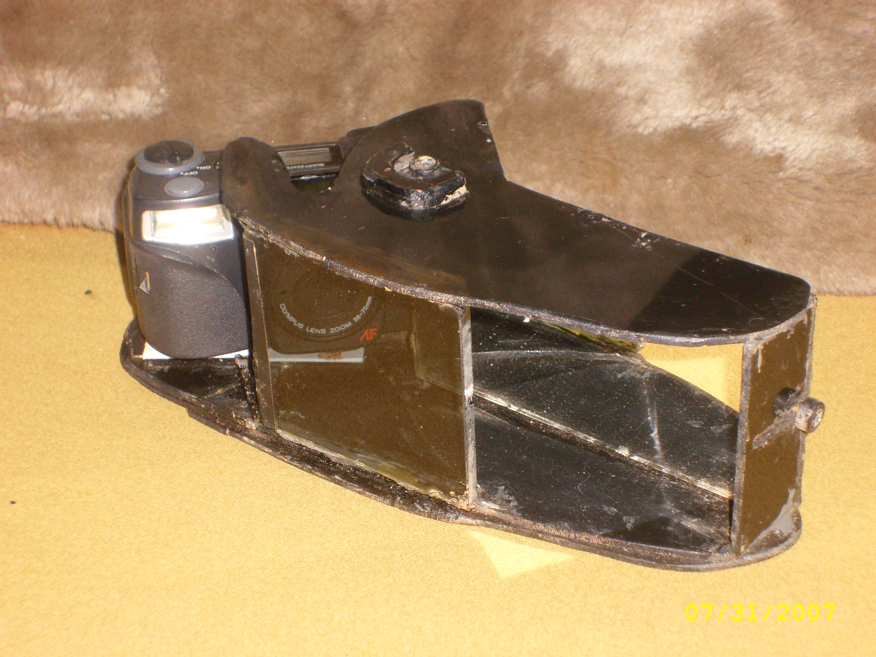
I used tinted plexiglas for the structure of the attachment, gluing the pieces together with epoxy, but wood or metal could also be used.
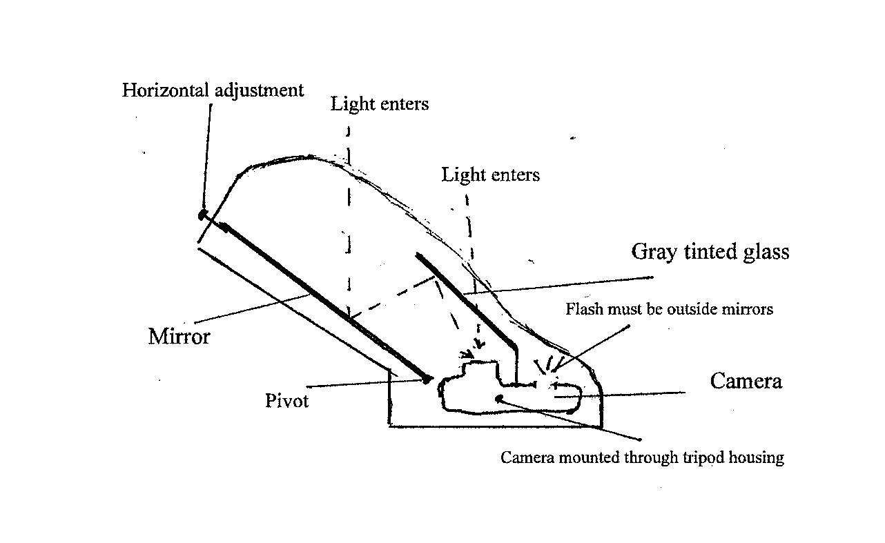
The idea is that the camera is mounted on the base with a piece of gray (neutral) tinted glass fixed at an angle in front of it. This allows light to go through to the lens, but will also reflect a very faint image from any light that hits the back side of it.
Beside the camera (to its left in my instrument), there is a longer mirror that extends beyond the fixed glass. Light then enters that space, hits the mirror, and then the back of the tinted glass, reflecting a faint (displaced) image into the lens (in addition to the stronger image that passes through the glass).
This mirror has a vertical pin glued to its back at the camera end, which sticks into a hole in the base, forming a pivot. Another pin protrudes through a slit in the top, allowing a vertical adjustment of the mirror.
At the other end of the mirror, a pin protrudes through a slit in the side, allowing horizontal adjustment of the mirror.
(Sizing and placing the mirrors is a little tricky and required, for me, trial and error. The tinted glass should be just large enough horizontally that its far (left, in my case) edge should be just beyond the range of the camera (the right edge should present no problem). Put the the camera on a table top and the tinted glass glass (about 3.5" in my case)about an inch in front of it. If you have a digital camera, turn it on and look at the image, assuring yourself that the right side of the glass cannot be seen. The glass should be more or less at a 45 degree angle, and the left side just barely shouldn't be seen either. Then put the other mirror to the left of the camera, and check to see that you can get a reflected image in it by pivoting it and turning it to make the two images coincide. It's not as complicated as it sounds.)
The mirrors should extend considerably higher than the top of the camera. Focusing the mirrors is done by sighting over the back of the camera through the tinted glass at the subject, and adjusting the tilt (vertical) of the movable mirror, and the horizontal adjustment, so that the two images coincide on the subject the camera is aiming at. Objects at different distances from the camera will then have a secondary, faint image displaced more or less from the main image, depending on how far in front of or behind they are to the main subject, and the subject will appear in a 3-dimensional space.
The tinted glass should not be very dark, first to allow more light to pass through to the lens, and secondly so that the reflected image will be just at the threshold of perception, not seen as such, but as a depth-clue for the picture to be taken. If the reflected image is too bright, the result is confusion, not a 3-D image.
Care should be taken to see to it that the flash of the camera is outside the mirrors (in my case, to the right), and the light is blocked from getting into the area of the mirrors. If not, the light reflecting off the glass and the mirrors will ruin any flash picture. It is not necessary for the little "radar" used as the range finder to be outside the mirrors. If it doesn't go through the glass, then it bounces off the mirror like the secondary light, adding perhaps an inch or two to the distance to the subject.
Note that this apparatus can also be attached to a video camera.
A much more sophisticated version (and a better one) of this could be done with electronics. The idea would be to use camera's "radar" range finder to do two (actually several) things: First, with its little target area in the center, it would focus on the center of interest, as now. But second, it would register the distance of objects in the field of view of the camera, and send this information back to the electronics of the camera.
What the electronics would then do is this: produce very faint secondary images to both the left and right of each image at a different distance from the focused image, the displacement depending on a mathematical formula.
The formula would make the displacement close to the eye slightly less than the distance between a normal pair of eyes, and it would get progressively smaller as the distance away from the eyes grew larger, until "infinity" (probably 50 feet or so, where there would be no displacement. In my paintings, I make a little "aura" around each figure both to left and to right, depending on perspective in this way. Obviously, when I paint a human figure at a distance, the "aura" is as wide as the separation of the figure's eyes. This seems to work in the paintings. But someone who knows perspective and can do math could figure out what our eyes actually do when we look at things, and translate this into the electronics, which would then create the proper "aura" throughout the field of view.
This would be a bit tricky, since the two eyes converge on the focal point, and so there would have to be displacements both before and after it, based on the distance in front of and behind the focal point, not really the distance behind the camera. Esperiments would have to be done to see what gives the most realistic effect.